
Apr 19, 2023
Eliminate noise with proper shielding and grounding
Shielding, grounding, and microphone cables
By Bill Whitlock
There is an old joke that the definition of a cable is “a source of potential trouble connecting two other sources of potential trouble” – that is worth chewing on. All signals accumulate noise as they flow through equipment and the connecting wires, and once noise has contaminated a signal it is essentially impossible to remove it without altering or degrading the original signal. For this reason, no system can be quieter than its noisiest link. Noise and interference must be prevented from entering any part of the signal path, and the most vulnerable areas are usually the signal interfaces.
The level of noise that is tolerable in an analogue pathway depends on many things but for a professional microphone – a primary signal source – most users would like it to be low enough to allow a dynamic range of >120dB. This means that noise and interference components must be 120dB below the maximum undistorted signal capability of the system.
Microphones in professional use are almost invariably connected using balanced cabling and so the many grave difficulties associated with unbalanced circuits and “ground” returns can be ignored. However safety “grounds” and “ground” connections concerning the shielding of balanced systems are highly relevant and it is worth considering the meaning of the term – and dispelling a good many of the myths attached to it.
Some myths
Some common fancies are that:
-
Earth grounds are all at zero volts both with respect to each other and to some mystical absolute reference point. They are not – and systems using multiple ground rods do not make noise disappear forever into the earth. They merely prove, rather pointlessly, that the soil resistance between the rods is considerably higher than the wire connecting them.
-
Wires have zero resistance. They don’t, so you cannot extend a zero-voltage reference to multiple locations in a system and thus eliminate voltage differences. Wires always have DC resistance so that even 3m (10ft) of thick 2.5 2mm (12#) copper measures a still significant 0.015Ω. In AC terms, the inductance will give the same wire an impedance of 30Ω at 1MHz. At 25MHz it will become a radio antenna and look almost like an open circuit. (Figure1)
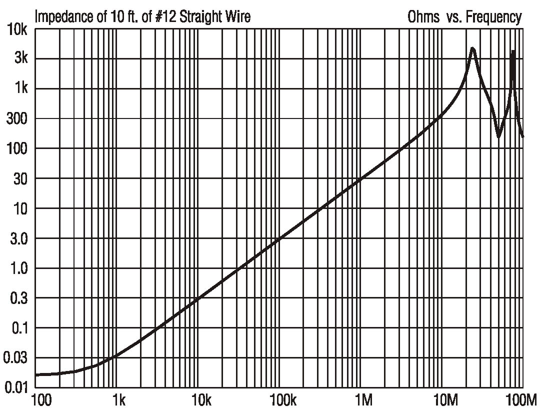
Fig 1—The impedance of 3m (10ft) of 2.5 2mm (12#) copper wire
Increasing the dimensions of the wire, even to ridiculous extents such as a 12mm solid copper rod, will make remarkably little difference. The AC impedance at 1MHz will still be about 25Ω and the DC resistance will never disappear completely. Using massive conductors to “short out” noise just does not work.
-
3. “Ground” connections must connect to earth. In fact, they do not need to have any physical connection to the earth at all (aircraft electronics get along fine without them) and they should be considered simply as electrical conductors that carry noise currents: they are fundamentally identical to the signal conductors.
Safety grounds
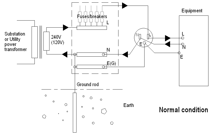
At this point, we ought to consider “safety grounds” because your life and everyone else’s depends on them. With the exception of valve (tube) power supplies, most microphones do not have an obvious connection to AC mains. However, the metal parts of microphones – the parts that you or an artist will touch – are usually connected via cable shields to the equipment chassis and metalwork of all of the rest of the audio system. The safety grounding of any of these parts is therefore of extreme importance. AC is delivered from a generator or transformer via a “Line” at about 240V or 120V (depending upon the country), and the current returns to the source via the “Neutral”. This concept of current flow is crucial – electrons always return, by any conductive path they meet whether intentional or accidental, to where they came from. The precise rules vary among countries, but it is standard practice to bond the Neutral lead of every circuit together and to an earth ground rod or metalwork such as a service cable shield. A safety “ground” connection is distributed with the power and connected to any exposed metal on a piece of equipment. (Figure 2)
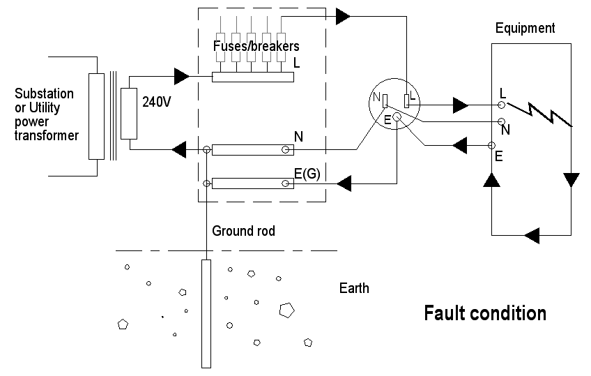
If a fault allows the metal to become “live”, the current will flow through the safety ground connection and return to the Neutral conductor at the bonding point. A high enough current should flow through this low-impedance circuit to blow a fuse or trip a circuit breaker in the Line side of the circuit. Note two things – the safety ground must return electrons to the Neutral conductor, and the connection to “earth” is irrelevant in this process. (Figure 3)
Any piece of equipment that uses a 3-pole power connector must be connected to an earthed outlet, and the integrity of the safety earth system should be beyond reproach. Where a reliable safety ground is not available, a Ground Fault Circuit Interrupter or Residual Current Device is an acceptable alternative. These monitor the balance in the current flowing in the Line and Neutral leads. Any difference is presumed to be leaking through a person and an internal breaker trips in milliseconds.
Disconnecting grounds by using a 3 to 2-prong adapter, “ground lifters” or removing the earth lead on a rewirable plug is both dangerous and illegal. It must never be done under any circumstances. With no safety ground connection, any fault current will flow through signal cable shields to any connected equipment. These cables may well melt and burn, and anyone touching the equipment risks electrocution. Have nothing to do with such systems.
Cable shields
The main function of cable shields is, of course, not to provide a lethal dose of AC but to help keep interference out of signal conductors. But to understand how that can be done, it’s necessary to have a clear grasp of how balanced circuits work. For a start, we all know that a balanced circuit uses twin conductors and that “each conductor is always equal in voltage but opposite in polarity to the other.… and this opposing polarity of the conductors is essential to its operation.” Except that this is also a myth. Each leg can be driven in antiphase, just one leg can be driven, or any option you fancy in between those two – signal symmetry is largely irrelevant to the noise rejection qualities of a balanced circuit. It is not the symmetry of the signal voltages that is useful but the impedance balance of the two conductors with respect to ground and to all other conductors.
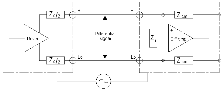
An ideal balanced circuit (figure 4) can reject any interference due to ground voltage differences, magnetic fields, or electric fields so long as it produces identical voltages in each of the signal lines and the resulting peaks don’t exceed the maximum input swing of the receiver. This voltage is labelled common-mode since it is common to both inputs. Traditionally, balanced audio interconnects use a shielded cable to connect the transmitting and receiving system grounds together and thus minimise the ground voltage difference between them, but the shield is not essential to the operation of the circuit and other techniques can be used to limit this voltage difference. Balanced receivers are differential devices and use a transformer or an amplifier that responds only to the voltage difference between its two inputs. Ideally, these devices will have no response at all to common-mode voltages but in practice that will not be the case. The ratio of the device’s differential gain to its common-mode gain is called the common-mode rejection ratio or CMRR. This is usually expressed in dB, the higher the better.
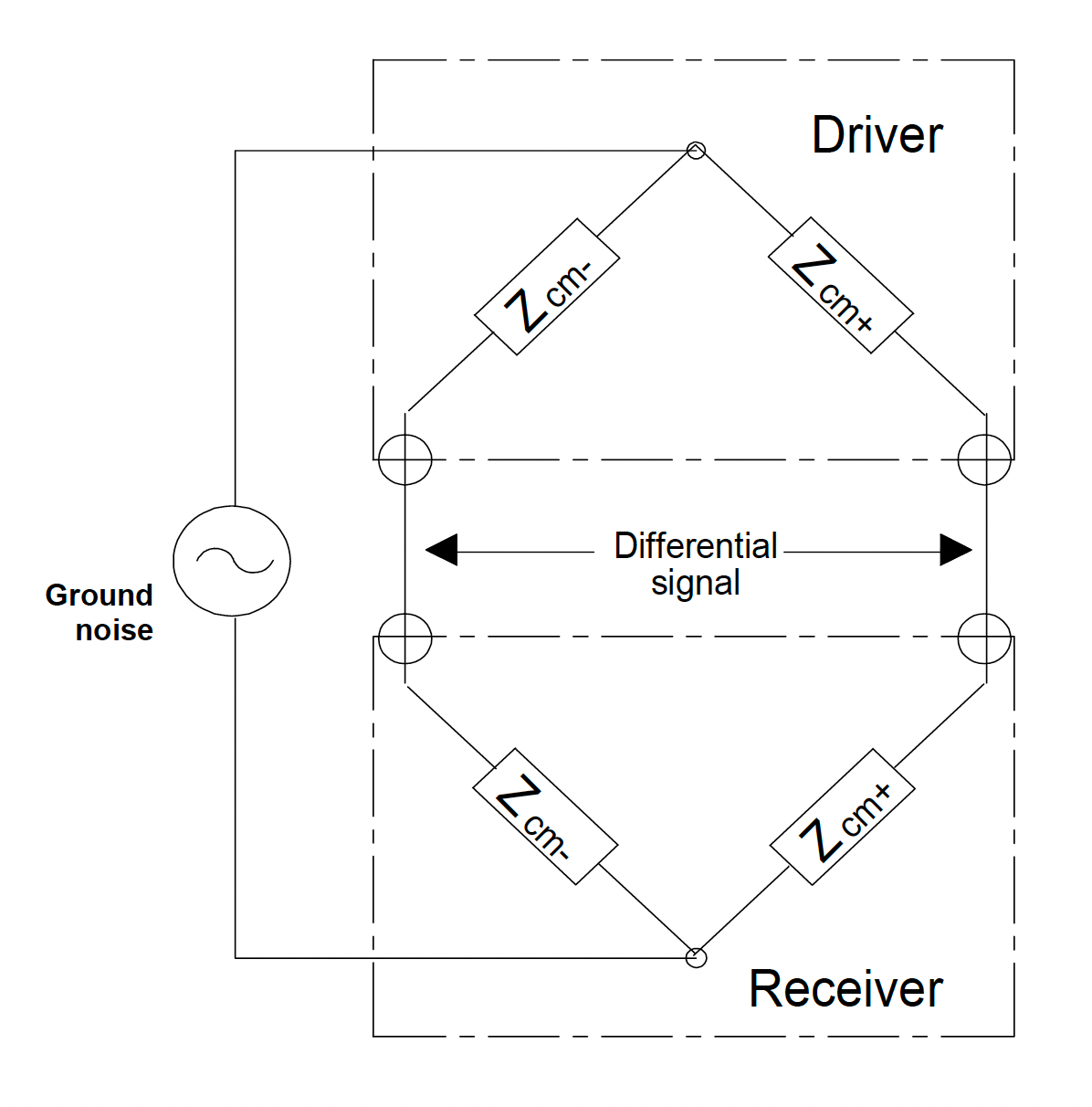
The Wheatstone bridge
The balanced circuit can be redrawn as a Wheatstone bridge of input and output common-mode impedances (i.e., with respect to ground), and ground noise as a signal source (Figure 5). If the bridge is not balanced or nulled correctly, a proportion of the ground noise will be converted to a differential signal at the “line” points. This nulling of the common-mode voltage is critically dependent on the ratio matching of these pairs of driver and receiver common-mode impedances. The nulling is barely affected by impedance across the line (the signal system or normal-mode impedance we sometimes see in a specification sheet) – only the common-mode impedances matter.
The bridge is most sensitive to poor nulling due to small impedance differences if its arms all have the same value. It is therefore possible to minimize CMRR degradation by making common-mode impedances very low at one end of the line and very high at the other. This fits in well with the concept of voltage matching – using a low-impedance driving circuit feeding into a high-impedance differential amplifier receiving circuit, rather than the older power-matching matched impedance technique. However, don’t confuse signal input impedance with common-mode impedance.
The sending end of the circuit (in this case the microphone line-driving circuit) should drive the output in “normal-mode” and not generate any common-mode signal. In practice, the balance of phantom extraction components, output resistors and, even worse, coupling capacitors will be imperfect, and some common-mode signal will be present. Imbalance in the microphone cable due to capacitive differences between the cores and shield will also exist.
To be as unaffected as possible by these bridge imbalances, the input of the microphone amplifier should have a common-mode impedance as high as is feasible. If it can be made as high as 10s of MΩ – something that is easily attainable with a transformer, though there are active circuit configurations that can approach this – then driver circuit and cable imbalances of 100Ω or more can be accepted without seriously degrading the CMRR. However, more conventional electronic input circuits with slightly mismatched RFI capacitors and phantom resistors may have common-mode input impedances of only a few kΩ and will be extremely sensitive to imbalances of even 1 or 2Ω. They will function as microphone amplifiers but they will perform very poorly in terms of excluding common-mode ground noise and will limit the practical dynamic range of the microphone/amplifier combination.
Shields, grounds and microphone cables
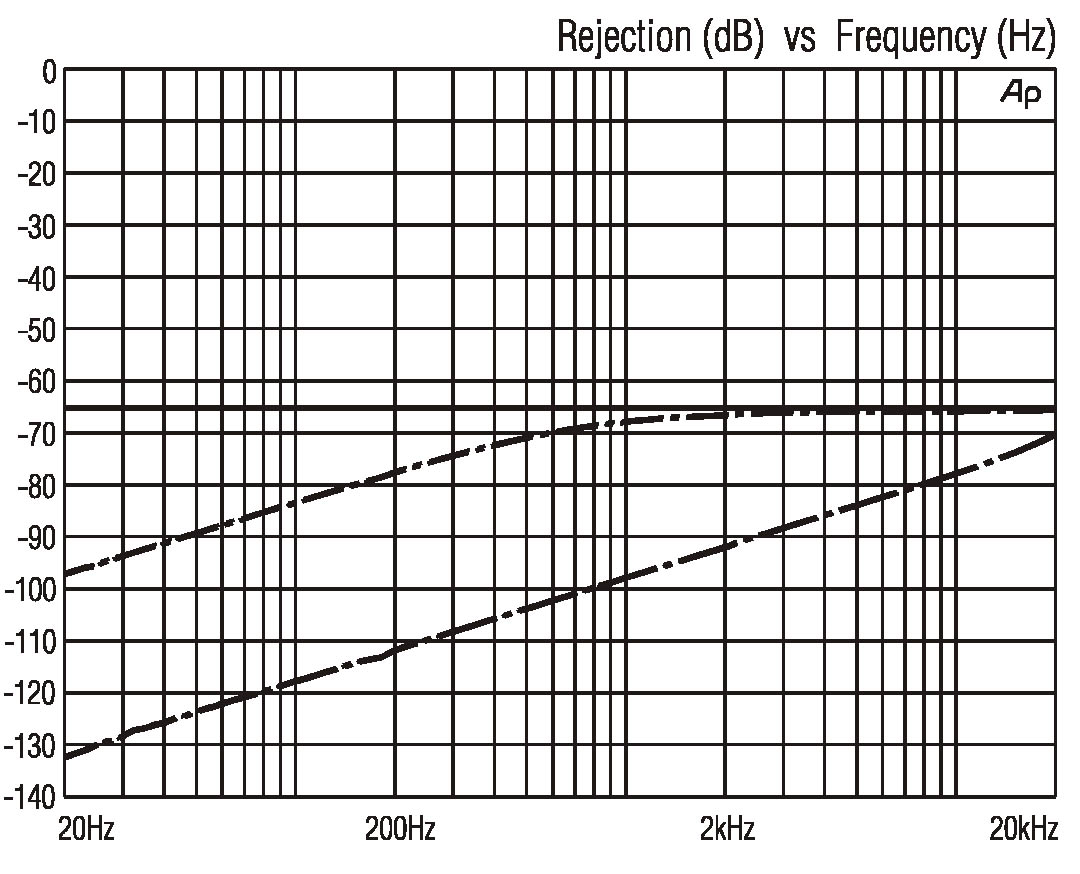
If capacitive components are present, CMRR deteriorates as frequency rises and a “good” ratio of 100dB at 20Hz will deteriorate by 6dB/ octave. This has important consequences where the ground noise has a fundamental frequency of 50/60Hz (as AC mains power does) and also harmonics that extend to several kHz. An acceptable CMRR at low frequencies may reject the clean hum but be quite inadequate to remove the objectionable higher-frequency buzz. The degradation of CMRR continues beyond the audio band limits and the CMRR at radio frequencies can be important since many amplifiers become non-linear beyond their intended band range. (Figure 6)
The cable
The cable between the microphone and the preamplifier needs careful consideration. Besides providing the two signal paths, a cable can provide shielding from electric and magnetic interference fields. Much of this involves the structure of the cable – the twist – and the form of the shield. With low-level microphone signals, both can be critical.
Capacitively induced interference from an electric field can be intercepted and diverted painlessly by a grounded shield. In practical terms, a shield which gives 85-95% coverage is adequate for balanced audio circuits. The manner in which a shield is connected can affect the CMRR of the system. In real circuits, all cables will have some capacitive mismatch between cores, and all drivers will have some mismatch in their output impedances. If the shield is only connected at the receiving preamplifier end, two mismatched low-pass filters are formed, and some of the common-mode noise will be converted to differential noise signal. If the shield is only connected at the microphone driving end, no filters are formed – all components are at the same (driver ground) potential.
Single-ended grounding of leads is rarely an option with microphones – phantom-powered ones obviously have to have a continuous ground connection. Double-ended grounding still tends to degrade CMRR but not as severely as receiver-only. It also prevents the cable from acting as a radio antenna and feeding high levels of RFI into the cable screen, which, though common-mode, will eventually be at least partially converted to differential-mode signal.
The twist
Twisting a balanced pair ensures that each conductor is exposed, as nearly as possible, to the same electric or magnetic field. In both cases, the interference component should be very nearly identical – common-mode – and therefore possible to reject if the receiving amplifier has good CMRR. Accurate twisting is the only method of dealing with low-frequency magnetic fields since screening is physically impossible with anything other than solid steel conduit. Starquad cable takes this a stage further by using very tight and accurately controlled twisting and averaging any induction across two cores on mutually opposite sides of the cable. This can provide about 40dB better immunity from magnetic fields than standard twisted pair.
Noise currents flowing in the shield itself can induce a voltage in the signal conductors magnetically. If the cable is perfectly symmetrical, this will be common-mode, but in real cables, there will be some inequality and hence a differential signal. Braided or counter-wrapped spiral (served), sometimes called “Reussen”, shields usually perform best and foil shield cables with drain wires the worst.
Long microphone cables are inevitably more prone to interference pickup than short ones. There will be some resistive signal loss too, but if the microphone source impedance is low and the preamplifier receiving one reasonably high, the loss will be small – no practical microphone cable is ever long enough to warrant being treated as a transmission line with matched impedances. The microphone output impedance and the cable capacitance form a low-pass filter so there may be some HF loss. Cables with a low self-capacitance will minimise this. In very long cables, the common-mode interference level generated may exceed the maximum signal capability of an electronic receiving preamplifier. In these cases, a transformer input has great advantages.
Transformers
An input transformer on a microphone line can cope with common-mode voltages as high as a few hundred volts – far higher than an active circuit – and also gives excellent immunity from RFI. Input transformers normally incorporate a copper Faraday screen to prevent capacitive coupling of common-mode signals from primary to secondary. The exceptionally high common-mode impedance of an input transformer allows it to provide a high level of CMRR and to be resilient to imbalances in the microphone circuit.
Many microphones incorporate an output transformer to provide balanced drive – and sometimes voltage gain on dynamics. These output transformers are different in design from input ones. They are likely to be bifilar-wound and will not use a Faraday screen since they need to maximise magnetic coupling to give good drive capability. Output transformers have a less significant effect on CMRR but will frequently be beneficial in reducing RFI pickup within the microphone circuitry.
It should be clear that maximum noise immunity in low-level balanced microphone circuits requires careful attention to the preventing of any imbalance. The use of loose tolerance components in such areas as phantom resistors, RFI filters and in-line pads or filters is likely to reduce CMRR drastically. A 1% mismatch results in a CMRR of only 40dB, so high precision is essential. This figure should not be confused with the actual noise level – that will vary with the level of interference trying to induce noise into the signal circuit. What it tells you is the likelihood of a poor signal-to-noise ratio under adverse conditions. With careful design, though, and rigid attention to detail, balanced microphone circuits can reliably have signal-to-noise ratios of 120dB.
To maintain the high dynamic range of these signals, the remainder of the chain must also be kept free of noise and interference. The techniques for doing this are beyond the scope of this article but are contained in various other documents by the author.
Further reading:
Morrison, R. & Lewis, W. – Grounding and Shielding in Facilities, 1st Edition, John Willey & Sons 1990
Morrison, R. – Solving Interference Problems in Electronics, 1st Edition, John Willey & Sons 1996
Muncy, N – Noise susceptibility in analogue and digital signal processing systems, Journal of the Audio Engineering Society, Vol 43, June 1995
www.jensentransformers.com has a list of many relevant articles.
Bill Whitlock has been president of Jensen transformers Inc (Van Nuys, CA) since 1989. He is widely known as a designer of signal interface systems and as an expert speaker on shielding and noise elimination at international seminars.
This article has been assembled by Chris Woolf from various articles by Bill Whitlock with his agreement and consent.
Originally published in 2010 by Microphone Data Ltd
© 2022 Micpedia