
May 02, 2023
Powering Microphones
Powering Microphones
By Chris Woolf
Simple dynamic microphones do not need any powering – they generate electrical energy from a relatively low impedance at a level that is adequate, if not generous, to feed a preamplifier at some distance down a cable.
Capacitor (popularly, though inaccurately, called “condenser”) microphone transducers do not generate energy but modify an electrical parameter, and have an extremely high output impedance which makes them impossible to connect directly to anything – even a short length of cable. This impedance needs to be reduced to a much lower value that will allow long microphone cables to be driven efficiently and will help to exclude interference. This impedance conversion, or matching, is carried out by an amplifier immediately behind the transducer – and this circuitry needs to be powered in some way.
Non-electret capacitor microphones (sometimes even more inaccurately called “true condensers”) also need additional power for polarising the capsule. RF designs use, instead, a small oscillator and demodulator in order to avoid some of the problems associated with high-impedance DC circuits but do not escape the need for power.
The field is even further complicated by the introduction of a few dynamic (including ribbon) microphones that have been allied to buffer amplifiers to give greater cable driving ability or a more consistent source impedance, though some would argue that in doing so they risk sacrificing the extreme Sound Pressure Level performance that most dynamics inherently possess.
The total power requirement for a microphone is commonly of the order of 100-200mW, though it might be as low as 50µW for some electrets, and nearer 500mW for some high output designs.
Microphones using valves (tubes, in US parlance) are something of a special case since their power-hungry circuitry normally requires purpose-made multi-rail supplies. There are a few examples where the power requirement has been reduced enough for a 48V phantom supply to be adequate, but they are a rarity.
And lastly, there is the newcomer – the digital microphone – with a requirement for not only powering of the analogue elements that it inevitably has but internal clocks, converters and digital control circuits. These do not come cheaply in terms of power – 2W is not uncommon.
Internal batteries
For the lowest power designs, internal batteries are an option – and can be very useful when sophisticated powering systems are not available. With rare exceptions, batteries are only used for electret designs where the current drain is just the impedance converter. A single AA cell is often the choice since it can fit into a slim-body barrel. The limitations of such systems are the need to switch the battery on and off (though some designs expect the user to simply remove it), per- haps check its capacity with some sort of LED indicator and the fact that the meagre power available does not allow large output voltage swings or very high cable driving ability.
Plug-in Power
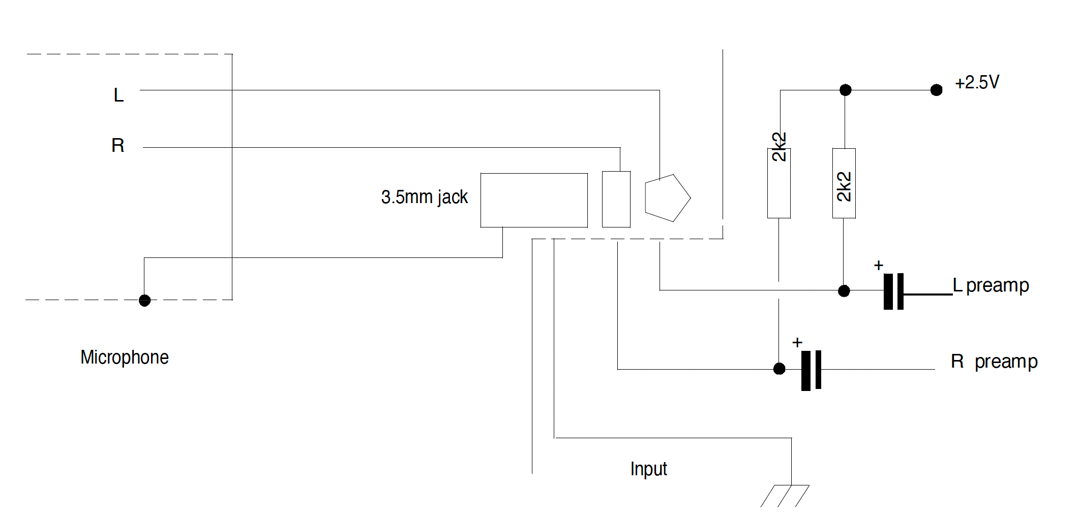
For microphones that are designed primarily for the domestic market and have an unbalanced output connection, the system known as “plug-in power” provides a comparable supply configuration – perhaps 10-20mW at <5V. In this case, the feed is from the device that the microphone connects to – usually a recorder of some form, though computers and mobile phones use a similar arrangement. The problems of battery switching and condition no longer apply but the restrictions on output and cable driving are unchanged.
Figure 1 shows a typical minidisk or video camera 3.5mm stereo jack input with powering circuitry.
Valve (tube) microphones
With the exception of the unusual phantom-powered devices, valve (tube) microphones are associated with a proprietary power supply unit, which connects to the microphone via a multiway cable. By definition, thermionic amplifiers need a heater supply and also a voltage of the order of 50-100V (sometimes greater) between the cathode and the anode (or plate). These supplies are fed on cores that are separate from the audio.
Capsule polarisation may be from the tube supply rail or a separate one. In many designs, a dual capsule is used and by altering the polarising voltage on each diaphragm the directivity can be changed. If the control for this is remoted to the power unit then still more cores are needed. Hence tube designs commonly use cables and connectors with 7 or more “ways”. This has the merit of simplicity even if it is mechanically and electrically somewhat heavyweight. More sophisticated arrangements are technically possible but examples are few and far between.
High voltage microphones
A few semiconductor microphones also use a proprietary power supply to generate clean rails as high as 120V. Semiconductors have the innate advantage of being able to run from voltages that are far lower than those that can be used with thermionic devices. Microphone amplifiers that operate on 1V can be designed and 12-48V is the most usual range for supply voltages (though an internal generation of higher polarising voltages may be used).
However, the design of a capsule that can work with extreme SPLs and an amplifier that can deliver very high levels of audio is eased if high-voltage rails are available. Thus a few highly-respected microphone designs have been introduced that trade these advantages for the inconvenience of non-standard connection systems.
T-Power
For the vast majority of semiconductor-buffered professional microphones, lower voltages and powers are considered adequate and two powering configurations cover virtually all of these – the rather rare T-power, and the almost ubiquitous phantom.
T-power (alias Tonader, Tonaderspeisung, A-B powering, or parallel powering) is nearly obsolete but still finds some adherents in the film and TV industry. It is an incompatible system, in that microphone lines using T-power must not be used for other microphones for fear of damaging them.
At the time of writing, the only T-power microphones marketed are the Sennheiser MKH416T and the Schoeps CMC4U preamplifier for the Colette range of capsules, but a considerable number of older Sennheiser designs are still in everyday use and other companies have produced T- power variants in the past.
Many users of T-power claim that it is more robust than phantom. This claim is a difficult one to prove since some of the alleged benefits are connected with the very low output impedance of T- power microphones in common use – something that is not exclusively their prerogative. It is also possible to operate T-power with poor cables that have an intermittent or non-existent screen connection. However, it might be better to be aware of such defects rather than oblivious to them.
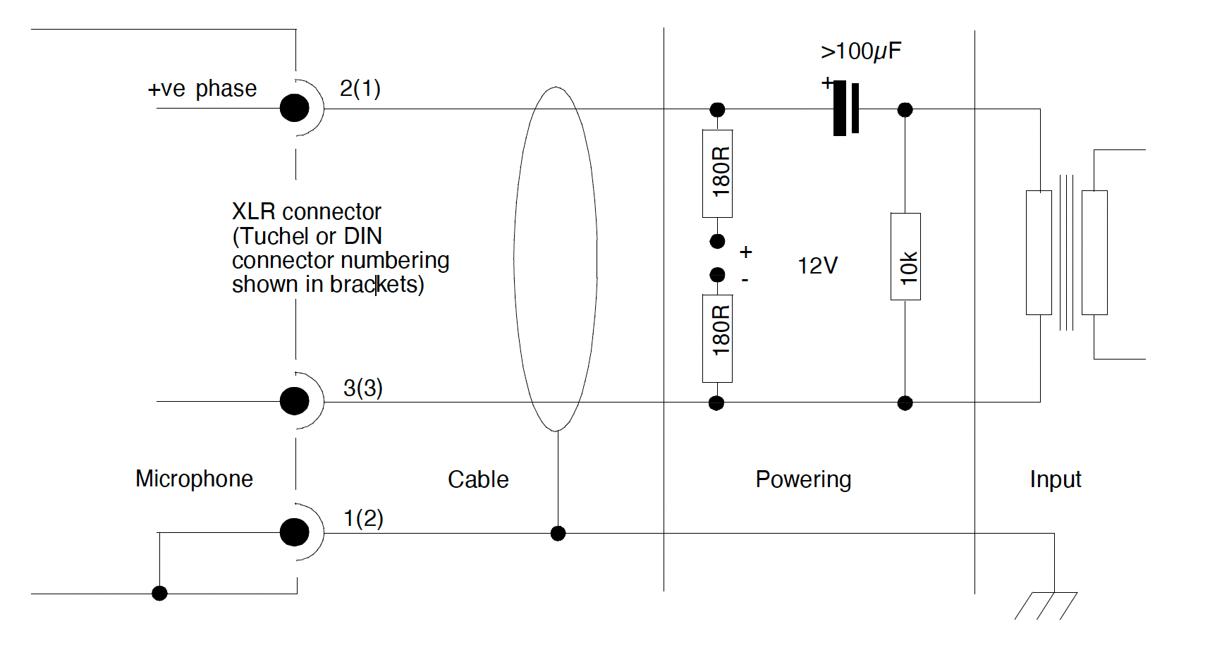
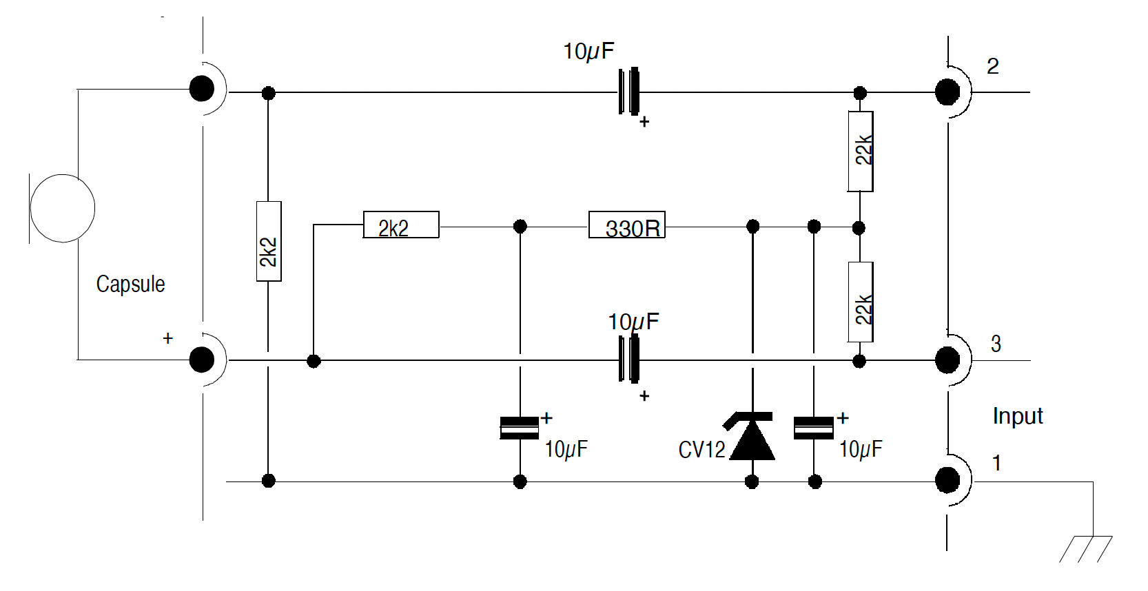
Parallel powering is covered by section 7.5 of the IEC 61938 standards. Figure 2 shows the usual circuit. It exists only in a 12V form, with the +12V being applied to the “positive” phase leg (XLR pin2, Tuchel pin1). However, some microphones have been made with reversed polarity for use with “positive” earth Nagra recorders.
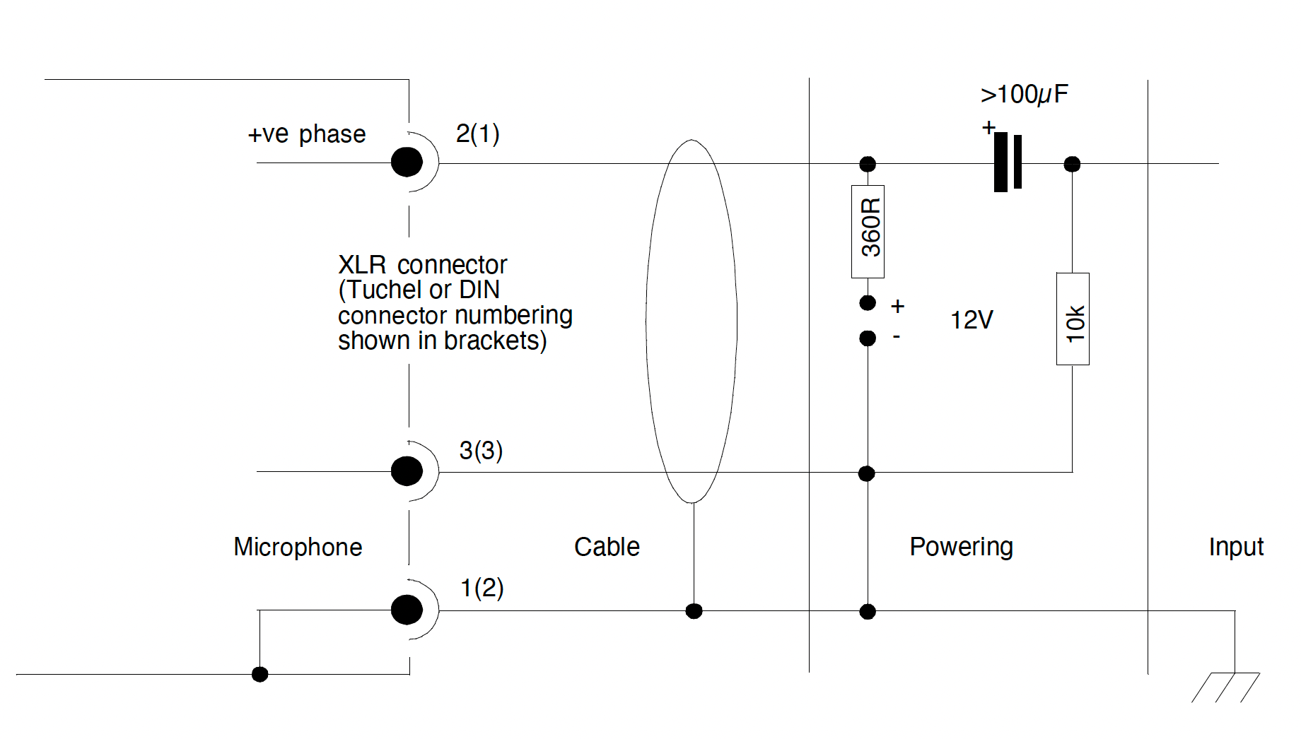
The 12V may be floating with respect to ground, which allows for a very simple connection to unbalanced systems. However, the standard also allows for one leg to be grounded. This may be more convenient in terms of symmetry for the audio signal. Figure 3 shows a variant of the normal circuit that permits an unbalanced connection with a grounded supply.
It should be noted that signal and powering polarity are unavoidably linked so the signal phase can only be changed by switching beyond the power section.
Besides the dangers of accidentally connecting microphone lines with T-power to dynamic, and particularly ribbon, microphones there are a number of other disadvantages that have contributed to its limited appeal. The supply voltage is superimposed on the signal voltage and therefore needs to be exceptionally well filtered. In multiple microphone systems the mutual decoupling – the isolation that prevents the leaking of audio signals via the common supply rail – must similarly be of a high order.
Historically many T-power location microphones were powered from portable regulated PSUs driven by a pair of miniature 9V batteries since mixers and recorders frequently did not have the necessary powering circuits. Many of these devices also usefully provided line and LF attenuation – functions that must be provided outside the powering loop.
Phantom Power
The phantom power system has become by far the most common microphone powering method and is an elegant and compatible arrangement. It takes its name from an ingenious technique used by telegraph engineers who realised they could treat a standard balanced pair as a single conductor and, by using an earth return, create an additional circuit without any extra wires. The phantom circuit so formed had no effect on the balanced pair since an identical phantom signal current flowed down each leg of this circuit. Balanced circuits cancel out such interference because they handle wanted signals as differential currents with opposite polarities on each leg.
Phantom powering of microphones gives the same immunity, so noise on the phantom power rails is rejected very efficiently. Thus the filtering and decoupling requirements for power supplies are significantly less critical and the risk of crosstalk between microphones on the same power rail is greatly reduced.
The standard for phantom power is IEC 61938 clause 7.4, and though the 48V version is the most common, a 12V variant is available and has some advantages where the economy of power is at a premium, as in portable equipment. A 24V version (P24) was introduced at one time but found no takers and is discontinued.
It would be possible to write a great deal about phantom power here but “The Feeble Phantom” article by Jörg Wuttke covers the subject with great authority and it would be much better for you to read it there.
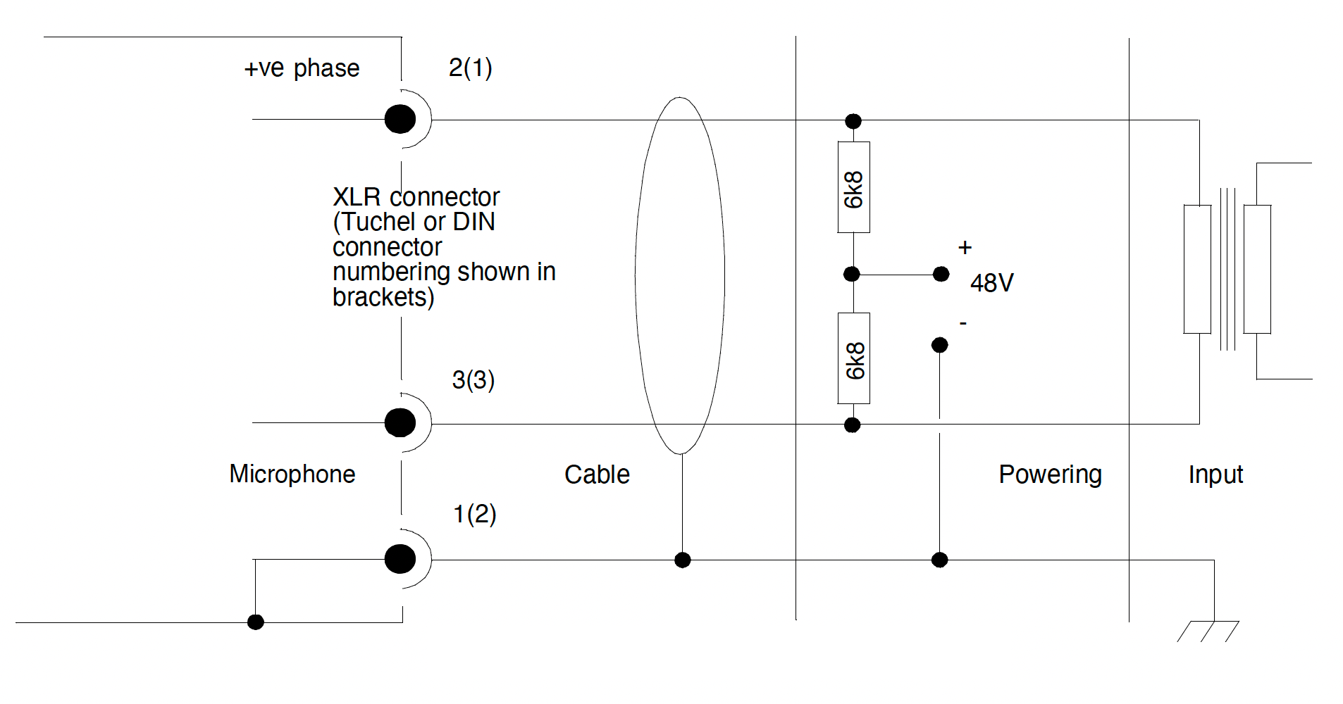
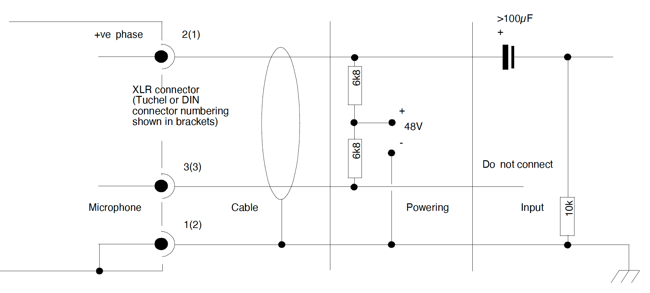
For reference, a standard 48V phantom – conventionally termed P48 – circuit is shown in Figure 4. Tuchel connections are shown as well as XLR although they are not met on current microphones.
Compatibility
Phantom power cabling is not polarity sensitive in terms of the signal and so phase inversion is possible at any point – something that may be useful in MS stereo recording rigs. It does however require that the cable screen connection is continuous and can provide a clean DC path. Where cables are correctly made up and maintained the connection of dynamic microphones intended for balanced operation poses no danger – no net current will flow within their coils and transformers.
Accurate matching is needed for phantom resistors both within the supply and the microphone in order not to restrict common mode interference rejection – >0.4%. is needed to achieve 60dB rejection. This matching is also needed for the series resistors of any line attenuator, but subject to certain limits such devices can be safely used within a phantom powering loop.
6k8Phantom powering is normally only used with fully balanced amplifier inputs. However, providing that the powering is balanced, the audio connection can be unbalanced in some circumstances, though the microphone’s output level and peak signal handling may well be compromised. Figure 5 shows a possible arrangement for a typical Class A DC coupled output circuit. Transformer and impedance-balanced outputs can also be connected in an unbalanced manner but will need different circuit arrangements.
Phantom powering of other microphones
The ubiquity of phantom powering means that it is often called upon to power microphones that are not essentially designed for use in this way. A number of small electret microphones – typified by lavalier designs – which are inherently unbalanced, and suitable for connection to radio transmitters and other non-standard inputs, may also be useful for operation with conventional balanced inputs. They can be converted to use with phantom supplies with some form of powering adapter. Figure 6 shows a possible configuration. Such adapters vary considerably in their sophistication. Some use additional semiconductor buffering to further reduce output impedance and thus improve the ability of the microphone to drive lines, while others use transformers. In many cases, the design also permits an option for battery powering.
However not every design achieves perfect line balance in both AC and DC terms, and some require rather unusual grounding arrangements at the capsule. This can give them a higher susceptibility to interference than might otherwise be expected.
Digital Phantom Power
The standard for digital microphones is gradually settling into a consensus that is described by AES42-2001. The reliability and compatibility of the phantom system commends itself for digital transmission paths just as it does for analogue ones.
The output voltage level of the data is 2V and the phantom voltage is fixed at 10V. The range of current anticipated is much higher than with analogue microphones – 50mA is considered a minimum and the maximum is 250mA (though 500mA has been mooted).
In theory, the cabling with its XLR-3 connectors is compatible with analogue microphones but the practicality of mixed analogue and digital environments has yet to be resolved.
Reference: The Feeble Phantom – Jörg Wuttke (Microphone Data 2003)
This article also draws on an earlier publication, “How to Power and Connect Professional Microphones” by Jörg Wuttke (Schalltechnik Dr.-Ing. Schoeps GmbH)
Chris Woolf was the editor of Microphone Data (the origins of Micpedia) and has a long association with Rycote. Originally published by Rycote Microphone Windshields Ltd for Microphone Data
© 2023 Micpedia